Electronic Warfare Operators
We are a group of Electronic Warfare Professionals with the Goal of Educating and Growing Multi-Domain EWO's!
Infrared Missile Principals
SpinScan Seekers: 1st Gen
The most common and simplest IR Seeker Type.
1) Use a Spinning Reticle
2)Uncooled PbS detectors in the 2-2.7 micron range.
As the Recital rotates the target and the background results in a different output for the Detector (Missile Seeker Head). This Output signal is a Sine-Wave. The Amplitude of the wave corresponds to the magnitude of Tracking Error. The Phase of the signal corresponds to the direction of the Tracking error. Coupled with a narrow bandpass filter the Tracker will only see the target at the specific micron range and not the background.
Conical Scan: 2nd Gen
This is also a Widely Proliferated IR Missile Type.
1) Rotating Optic, Instead of Reticle
2) Cooled PbS detectors allowing operations in the 3-5 micron range.
This Generation of seeker removed the On-Axis insensitivity of 1st Generation IR, by Rotating the Optics Instead of the Reticle.
This Rotation led to the ability to Track the Target via its Frequency Modulated. (Off Axis Distance) "Think Time measuring when thinking FM"
Pick off gives Phase Variation= Location of Target in the FOV.
Rosette Seekers: 3rd Gen
A common seeker type found on such missiles a the Stinger and SA-18.
1) Psuedo-imaging seeker which creates an image of the target by moving the IR signal over the Detector. There are other types of scans, but the Rosette scan is most common.
2) Multiple Bands of IR & even UV bands are typically used by the Detector. Most Common SWIR/MWIR. This results in better discrimination of Targets vs Background.
SWIR= Higher Resolution
MWIR= Increased Temperature Sensitivity
3) InSB cooled seekers with CdS to cover into the UV spectrum.
Imaging Seekers 4th: Gen
Not as common, but used by the Better Equipped Militaries (NATO, Russia, USA, etc)
1) Uses a Focal Plane Array and produces an Image of the Target.
2) A computer and Algorithm compare the Image (close to digital) to a database and determine if it is the target vs a decoy or background.
Good Video of the Seeker: Iris.ogv
Air-Air Missiles: Infrared
AIM-9
The AIM-9 has many generations. The Current AIM-9X is One of the most Advance Missiles.-Capable of Off Bore-sight.
-Helmet Mounted Cue'd.**AIM-9 **-Video
**AIM-9X **-Video
.....
AA-11
Russian Design, with many versions and Upgrades. Direct Competitor to AIM-9.-Capable of Off Bore-sight.
-Helmet Mounted Cue'd.AA-11 Iranian Test Fire-Video
Radar Scans, Patterns, & Resolution Cells
The pattern or scan type is a product of the Radars designed intent. From a common circular scan for large VHF Early Warning Radars to Raster Scans used on most modern Target Engagement Radars.
Scan Types
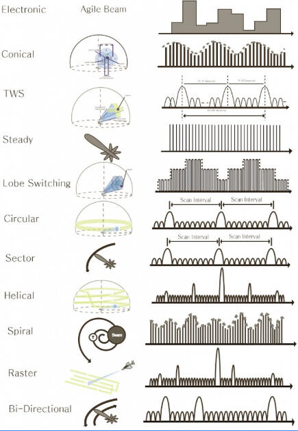
Scan's are Important to the mode or objective of the Radar. Therefore certain Scan Types are used for Certain Designs/Functions.The Scan Type causes (as seen in the picture above) a Time measurement that is in addition to the radar mile time measure.
Additionally it is key in determining a targets bearing and volume of sky scanned.
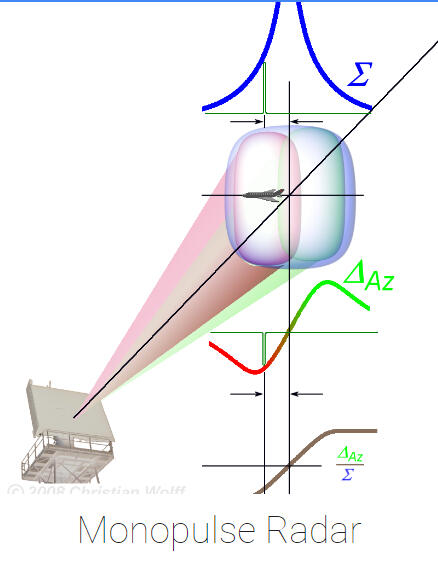
Mono Pulse Radar
A Pulse (or multiple) are sent from the same Radar Set (or nearby)-Reflected from the Target- Received by the Same RADAR Set.
Circular Scan Radar Changing Elevation
Sequential Lobing
Conical Scanning
Radar Estimation
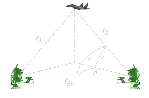
Bi-Static Radar
A Pulse is Sent from a Radar Set, then it is received by a Second Receive Set. Which is Geographically Separated.
The Second Set Measures Angle and Time of Receipt. Then compares to Time of Transmission.**It is very Effective Against Common Notching Tactics and Low Observables.
Radar Resolution Cell
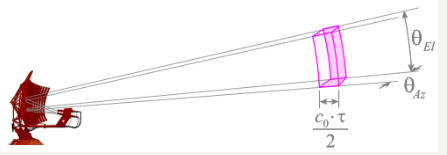
Radar Resolution Cell is the smallest volume in the radar's coverage area in which two or more targets can be distinguished by the radar. The resolution cell size is determined by the radar's range resolution, azimuth resolution and elevation resolution.
Azimuth Resolution is the ability of a radar system to distinguish between two objects that are in close proximity to each other in the horizontal plane. It is often measured in terms of the minimum angle between two objects that can be distinguished by the radar.Elevation Resolution is the ability of a radar system to distinguish between two objects that are in close proximity to each other in the vertical plane. It is often measured in terms of the minimum angle between two objects that can be distinguished by the radar.Range Resolution in radars refers to the ability of a radar system to distinguish between two or more targets that are located at different ranges, but at the same azimuth and elevation. This is an important characteristic of radar systems, as it determines the minimum distance between two targets that the system can distinguish. The range resolution of a radar system is determined by its pulse duration, or the time it takes for the radar to transmit a single pulse, and the pulse repetition frequency (PRF), or the rate at which the radar transmits pulses.
A radar system with a shorter pulse duration will have a better range resolution than one with a longer pulse duration. This is because a shorter pulse will have a narrower bandwidth, and will therefore be less affected by Doppler shifts caused by moving targets. Additionally, a radar system with a higher PRF will have a better range resolution than one with a lower PRF. This is because a higher PRF allows the radar to transmit more pulses in a given time period, providing more information about the target's range.
The range resolution of a radar system can be calculated using the following formula: Range resolution = c / (2 * Bandwidth)
Where c is the speed of light and Bandwidth is the pulse bandwidth. This formula shows that the range resolution is inversely proportional to the pulse bandwidth.
It's important to note that the range resolution of a radar system is also affected by other factors such as the signal-to-noise ratio and the environment, and that different types of radar systems have different range resolution characteristics. For example, pulsed radar systems have better range resolution than continuous wave radar systems. Additionally, radar systems that use synthetic aperture techniques, such as synthetic aperture radar (SAR), can have much higher range resolution than conventional radar systems.
In conclusion, range resolution is a critical parameter for radar systems and it is determined by the pulse duration, PRF, and pulse bandwidth. It is inversely proportional to the pulse bandwidth, the shorter the pulse duration and the higher the PRF, the better the range resolution. Other factors such as signal-to-noise ratio and environment also affect the range resolution.
Electronic Warfare in the Area of Operations
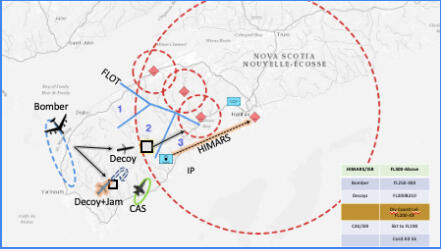
When considering Area of Operations, it must be defined by the Echelon and Region. Some assets are Strategic other are Tactical and Electronic Warfare has a tendency to Effect Large Areas.The image to the Left is an example of Assets Employed at the Division in support of CAS; which is supporting a Tactical Level Objective.Is the AO the Battalion, Brigade or Division? Does an ASOS control the Air assets or is an AOC?...All of this is something that must be discovered by commanders and communicated appropriately. Before Execution.....
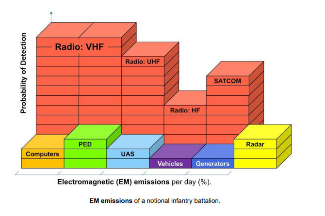
A Typical Battalion Electromagnetic (EM) emissions per day.
As you can see the Average Troop Talking on the Radio is the biggest Emissions Percentage.If the Unit doesn't control this it is exploitable by you or the enemy.

Electronic Warfare Kill Chain
As you can see a Military can Control or Use the Electromagnetic Spectrum. Either preventing itself from being a Target or Making itself a Valid & Easy Target.
Electronic Attack (EA)

It is the Offensive Component of Electronic Warfare aimed at controlling the Electromagnetic Spectrum through Force. Commonly called Jamming it involves the following critical principles of Control: Deceiving, Disrupting, Delaying, Degrading or Destroying the Enemies Capabilities in the Electromagnetic Spectrum.EW Anaylsis-Ausairpower.comRadar Jamming-NI Radar Video Series
Jamming Techniques

Noise Jamming
This category of Jamming is Aimed at Raising the Noise Floor. Overpowering Victim Signals with their own.BarrageSpotSwept Spot
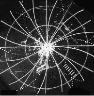
Deceptive (Repeater) Jamming
A more modern category of Jamming which uses computer processing to mimic signals. DRFM falls into this Category primarily, However Noise Jamming can be modulated at Rates to provide Deception Jamming.Digital Radio Frequency Memory Techniques:MFTVGPORGPO
Noise Jamming


Barrage Jamming: A Jammer is applied across a wide bandwidth. Resulting in a cover of a wide area, but loss of power. This is best for Frequency Agile Radars and at Range.
Advantage: Wide Frequency Covered and potentially multiple threats.Disadvantage: Burnthrough will happen at a further range.
Spot Jamming: The act of concentrating a Jammer on a narrow Bandwidth. Raising the noise floor on the targeted threat significantly.
Advantage: Increased power per threat and more effective in close (Closer Burnthrough).Disadvantage: Focus is on one threat at a time and can become labor intensive for the EWO.
Swept Spot: This is the same as Spot Jamming, except to cover multiple frequencies or frequency agile radars Jamming; the Spot Jamming is moved across multiple frequencies. Targeting one threat per time period.
Advantage: Effectively Covering Multiple Frequencies and Threats.Disadvantage: Threats go uncovered for periods of time. This may lead to detection and targeting.
Digital Radio Frequency Memory (DRFM)
DRFM Techniques
Range Gate Pull Off- emsopedia.com
Vertical Gate Pull Off- emsopedia.com
Cross-Eye- emsopedia.com
DRFM: Is simply defined as recording a signal, then Altering it and repeating it back to the Threat.
Advantage: Significantly harder to counter with conventional ECCM techniques and just as difficult the detection.Disadvantage: Less power, less noise in the environment. So once countered effectively it has little to no degradation to the threat system.Additionally difficult and expensive to engineer, maintain, and field.
DRFM Techniques
• Range Domain: Range Gate Pull Off (RGPO), Range Gate Pull In (RGPI),
• Doppler Domain: Velocity Gate Pull Off/In (VGPO/I)
• Range/Doppler: Coordinated RVGPO
• Multiple False Targets (MFT):
◦ Range: Multiple RGPO/I
◦ Doppler: Multiple Doppler False Targets (MDFT)
◦ Range/Doppler: Multiple Range Doppler False Targets (MRDFT), Coordinated RVGPO
◦ Spoofing (coherent or not-coherent false targets)
• Amplitude Domain: On Off (or swept amplitude modulation), Count Down
• Angle Domain: Inverse Gain, Beam Scan Modulation (Fixed or Swept Poke up gate), Cross Eye , Cross Pol
Mechanical Jamming
Mechanical Jamming: The use of Chaff; Corner Reflectors and Decoys to Deceive or Saturate (Disrupt) the Threat.
Chaff: can cover a Single Aircraft or Entire Formations.Corner Reflectors can be installed to Deceive positions or direction of travel.Decoys: typically mimic and Actively Deceive routes and Posturing.
Exploiting Radar limitations
Radar Beaming & Notching
The intent is to Exploit a Doppler Radars Velocity Tracking by minimizing Closure.This Technique is also useful against Pulse Radars who have Moving Target Indicator (MTI) Filters. As many modern radars come equipped with.At minimum a Notch or Beam will stop closure and give you time to maneuver more advantageously.It should be noted that your Velocity of Closure (Vc) does not need to be zero. You must only fall below the radial velocity for a particular Radars Doppler Frequency Shift (Khz).
Doppler Radar Formulas-Brad Muller
Doppler Filter-Radar Tutorial
MTI & Doppler Processing-MIT Lecture
Radar Min Range & Radar Range Resolution
Radar Range Resolution: =1/2PW
Radar Min Detection Range: =1/2PWThe Radar Range Resolution allows for more than one Target to advance together and only be seen as one target.
Example: Tall King A: Pulse Width=10 µs
0.510=5 µs. This converted to distance in a light mile= 1500meters.Radar Cone of Silence: This is the gap by max elevation the Radars Scan. Either by Beam limitations or Elevation in Scan.**Sometimes a Radar has different gaps in detection at various Ranges, Which may be exploitable.
Radar Blind Speed is speed at which the target can not be measured by the radar. This occurs because of the relationship between the transmitted pulse repetition time (PRT) and the received pulse-repetition rate.A radar will have multiple blind speeds based on a Radars PRF, However many counter this with a staggered PRF.... (See Video on this slide).
Radar Horizon
Due to the Curvature of the Earth Radars have limits in Range in which they can see.The Elevation of a beam also can reduce a radars Rmax.Propagation & Antennation can either Aide or Hamper a Radars Range.
Positioning and Radar Cross Section
Positioning and Radar Cross Section is the key concept in Low Observables.There are only two things controllable by the target in the Radar Range Equation: Range & RCS. Because of this positioning yourself in a manner to minimize your RCS resulting in Minimizing detection is key.This is a 3 dimensional problem. As can be seen in the images to the left.
Therefore most aviators real time try to use waterlines, however with detailed planning or real-time planning this may be alleviated.
Exploiting Radar: Part 2
As the Radar Signal is propagated away from the Radar, the direction of propagation (Antennae Angle) will effect its detection.As seen in the Vertical Coverage Diagram (VCD or Blake Chart) you can see how this affects the detection capability of a RADAR.As the Aircraft enters in close range it enters the Cone-Of-Silence. Resulting in not being detectable by the radar.*For many Long Range Early Warning Radars the Cone-Of-Silence can often be larger than 20 km's.


